
1. Rhagymadrodd
The KELUSHI XQ-350 Wire Tracker is a versatile tool designed for telecommunication network line engineering, routine servicing, and computer network line maintenance. It assists in tracing wires, verifying LAN cable conditions, and performing continuity tests on various metal wire lines.
Cynnwys Pecyn
Wrth agor y pecyn, gwiriwch fod yr holl eitemau canlynol yn bresennol:
- 1x Emitter Unit
- Uned Derbynnydd 1x
- 1x Earphone
- 1x RJ11 Adapter Cable
- 1x Alligator Clip Adapter Cable
- 1x RJ45 Adapter Cable
- 1x Llawlyfr Defnyddiwr (y ddogfen hon)
- 1x Toolkit/Carrying Case

Figure 1.1: KELUSHI XQ-350 Wire Tracker and included accessories.

Figure 1.2: The carrying case and a list of its contents, ensuring all components are accounted for.
2. Nodweddion a Swyddogaethau Cynnyrch
The XQ-350 Wire Tracker offers a range of functionalities to assist in network and telephone cable management:
- Olrhain Gwifren: Locate telephone wires and LAN cables within electrical systems.
- LAN Cable Verification: Assess the condition of LAN cables, identifying open circuits, short circuits, and cross-connections.
- Prawf Parhad: Perform basic continuity checks on cables.
- Arwydd Batri Isel: Alerts the user when battery power is low.
- Flashlight LED Integredig: Provides illumination in dark working environments.
- Cable Assignment Test: Specifically tests 2-wire (RJ11) and 4-wire (RJ45) telephone cables for open, short, and cross faults.
- Cable State Testing (2-wire): Detects DC line voltage, determines anode/cathode polarity, and identifies ringing signals.
- Target Wire Identification: Quickly find specific wires among bundles of telephone or network cables by comparing sound volume and signal indicator brightness.
- Ethernet Switch/Router Compatibility: Capable of finding wires connected to operating Ethernet switches, routers, or PC terminals.
3. Adnabod Cydrannau
3.1 Emitter Unit

Ffigur 3.1: Blaen view of the Emitter unit with key components labeled.
The Emitter unit features:
- Porthladd RJ11: For connecting telephone cables.
- Porthladd RJ45: Ar gyfer cysylltu ceblau rhwydwaith.
- Wire Finding Indicator (STATUS): LEDs indicating the status during wire tracing.
- Function Switching Button: Yn cylchdroi trwy wahanol ddulliau prawf.
- Function Selector Switch: Toggles between SCAN, OFF, and TEST modes.
- Wire Sequence Indicator (1-8, G): LEDs that light up to show cable continuity and wiring sequence.
- Testing Indicator (VERIFY): Indicates the result of cable verification.
3.2 Uned Derbyn

Ffigur 3.2: Blaen view of the Receiver unit with key components labeled.
The Receiver unit features:
- Archwiliwr: Used to detect the signal emitted by the Emitter.
- Dangosydd Signal: Visual indication of signal strength.
- Inching Button (PUSH TO TEST): Activates the signal detection.
- PWR-VOL Switch: Power and volume control for the receiver.
- Jack clustffon: For connecting the included earphone for clearer audio detection.
- Volume Adjuster: Yn rheoli lefel allbwn sain.
- Spotlight Switch: Yn actifadu'r fflacholau LED adeiledig.
- Wire Sequence Indicator (1-8, G): LEDs mirroring the Emitter's indicators during cable testing.
- Porthladd RJ45: For connecting network cables during testing.
Ffigur 3.3: Manwl views of the RJ45/RJ11 ports, probe, power switch, and speaker on the XQ-350 units.
4. Gosod
4.1 Gosod Batri
Both the Emitter and Receiver units require a 9V DC battery (not included) for operation.
- Locate the battery compartment cover on the back of each unit.
- Llithrwch neu ddadglipiwch y clawr i agor yr adran.
- Connect a 9V battery to the battery clip, ensuring correct polarity.
- Rhowch y batri y tu mewn i'r adran a chau'r clawr yn ddiogel.

Figure 4.1: Open battery compartments of the Emitter and Receiver, showing where to insert the 9V laminated battery.
4.2 Cysylltu Ceblau
Use the appropriate adapter cables (RJ45, RJ11, or alligator clips) to connect the Emitter to the cable you wish to test or trace. The Receiver is used to detect the signal or verify the cable status.
5. Cyfarwyddiadau Gweithredu
5.1 Wire Tracing (SCAN Mode)
This mode is used to locate a specific wire among a bundle of cables.
- Connect the Emitter to one end of the target cable using the appropriate adapter (RJ45, RJ11, or alligator clips).
- Set the Function Selector Switch on the Emitter to 'SCAN'. The 'STATUS' indicator will light up.
- Turn on the Receiver by adjusting the PWR-VOL switch. Adjust the volume to a comfortable level.
- Use the Receiver's probe to scan the cables at the other end or along the cable path.
- When the probe is near the target wire, the Receiver will emit an audible tone. The signal indicator LEDs will also light up.
- The target wire is identified by the loudest tone and brightest signal indicator.
- For clearer audio, connect the earphone to the Receiver's headset jack.
5.2 LAN Cable Testing (TEST Mode - RJ45)
This mode verifies the wiring sequence and identifies faults in RJ45 network cables.
- Connect one end of the RJ45 cable to the Emitter's RJ45 port and the other end to the Receiver's RJ45 port.
- Set the Function Selector Switch on the Emitter to 'TEST'.
- Observe the Wire Sequence Indicator LEDs (1-8, G) on both the Emitter and Receiver.
- Cysylltiad Arferol: LEDs on both units will light up sequentially from 1 to 8, then G (ground), indicating a correct wiring sequence.
- Cylchdaith Agored: If a specific LED (e.g., '3') does not light up on either unit, it indicates an open circuit on that wire.
- Cylchdaith Fer: If two or more LEDs light up simultaneously or out of sequence, it indicates a short circuit between those wires.
- Cross-Connection: If the sequence of LEDs on the Receiver differs from the Emitter, it indicates a cross-connection.
5.3 Telephone Cable Testing (TEST Mode - RJ11)
This mode is used for 2-wire telephone cables to check continuity and state.
- Connect one end of the RJ11 cable to the Emitter's RJ11 port using the RJ11 adapter.
- For cable state testing, connect the other end of the RJ11 cable to the line you wish to test.
- Set the Function Selector Switch on the Emitter to 'TEST'.
- Line DC Detecting and Anode/Cathode Determination: The Emitter will indicate the presence of DC voltage and its polarity.
- Ringing Signal Detecting: The Emitter can detect if a ringing signal is present on the line.
- Open, Short, and Cross Testing: Similar to LAN cable testing, the LEDs will indicate faults.
5.4 Defnyddio'r Fflacholau LED
The Receiver unit includes a built-in LED flashlight for working in dimly lit areas.
- Locate the Spotlight Switch on the side of the Receiver unit.
- Slide the switch to the 'ON' position to activate the flashlight.
- Slide the switch to the 'OFF' position when not in use to conserve battery life.
6. cynnal
6.1 Batri Newydd
When the low battery indicator illuminates or the unit's performance degrades, replace the 9V battery in both the Emitter and Receiver units as described in Section 4.1.
6.2 Glanhau a Storio
- Clean the units with a soft, dry cloth. Do not use abrasive cleaners or solvents.
- Storiwch y ddyfais mewn lle oer, sych, i ffwrdd o olau haul uniongyrchol a thymheredd eithafol.
- If storing for an extended period, remove the batteries to prevent leakage and damage to the device.
7. Datrys Problemau
7.1 Dim Pŵer
- Ensure the 9V battery is correctly installed with proper polarity.
- Amnewid y batri gydag un ffres.
- Check that the power switch (PWR-VOL on Receiver, Function Selector on Emitter) is in the 'ON' or 'SCAN'/'TEST' position.
7.2 No Signal During Wire Tracing
- Verify the Emitter is set to 'SCAN' mode.
- Ensure the Emitter is properly connected to the cable.
- Adjust the Receiver's volume to maximum.
- Confirm the Receiver's probe is in close proximity to the target cable.
- Check for excessive electromagnetic interference in the environment.
7.3 Incorrect Cable Test Results
- Ensure both ends of the cable are securely connected to the Emitter and Receiver.
- Verify the Emitter is set to 'TEST' mode.
- Archwiliwch y cebl a'r cysylltwyr am ddifrod gweladwy.
- Test with a known good cable to confirm the device is functioning correctly.
8. manylebau
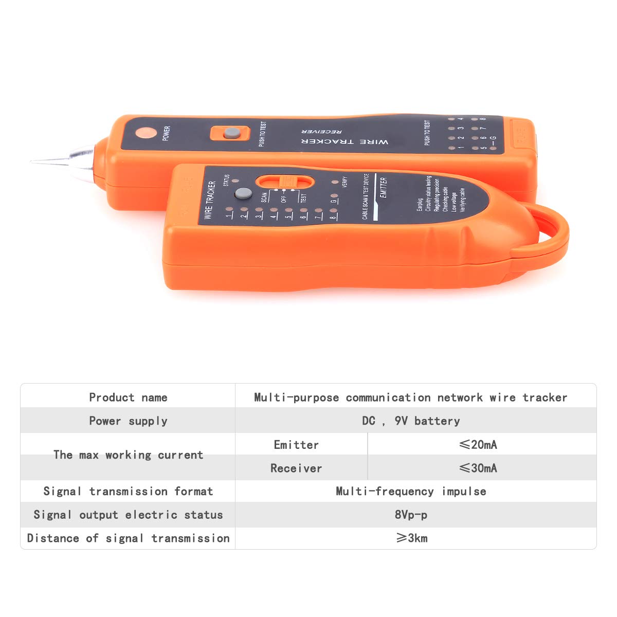
The following table outlines the technical specifications for the KELUSHI XQ-350 Wire Tracker:

Figure 8.1: Visual representation of the KELUSHI XQ-350 Wire Tracker's key specifications.
| Paramedr | Gwerth |
|---|---|
| Model | XQ-350 |
| Cyflenwad Pŵer | Batri DC 9V (heb ei gynnwys) |
| Working Current (Emitter) | ≤10mA (Test mode) |
| Working Current (Receiver) | ≤30mA |
| Signal Transmission Format | Multiple frequency pulse |
| Signal Output Electric Status | 8VP-P |
| Distance of Signal Transmission | ≥3km |
| Lliw | Oren |
| Deunydd | Plastig ABS |
| Dimensiwn Allyrrydd | Tua. 12.8 × 4.5 × 2.5 cm |
| Dimensiwn Derbynnydd | Tua. 17.5 × 4 × 2.2 cm |
| Pwysau Eitem | 250 gram |
9. Cefnogaeth
For any questions or assistance regarding the KELUSHI XQ-350 Wire Tracker, please contact the manufacturer or seller. Refer to your purchase documentation for specific contact details.